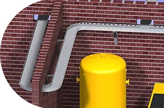
3D Pipe System Planning with Smap3D Piping
Using Smap3D Piping
3D pipe system construction working method
A user draws and defines the required pipe system route as a programmed toolpath with 3D lines (basic functions in the CAD system). Smap3D piping analyses the earmarked line elements and composes the pipeline paths automatically from the logical criteria. A pipeline path describes the route of a 'continuous' pipe system from one connection to another, regardless of how many interjacent line elements the path is made up of. Further new pipeline paths begin at each branch. Pipeline paths are associative with the drawn 3D line elements of the CAD system. Pipeline paths form the basis for the generated 3D pipeline, made up of fittings and pipes.
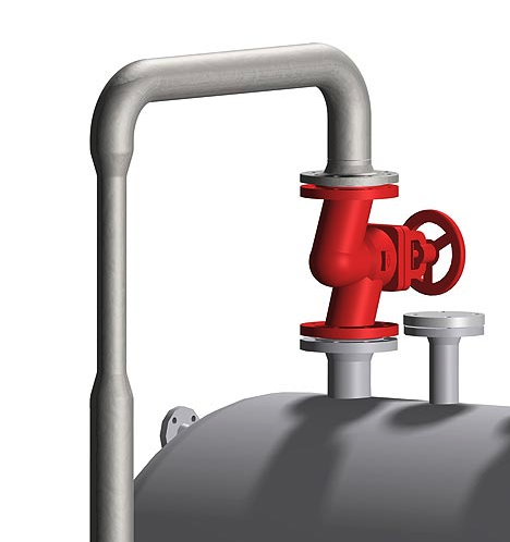
In pipeline construction with pipe specs, Smap3D Piping automatically generates the complete pipe system according to the required pipe spec, its diameter, as well as other pipe system characteristics. In the process, the software adopts the automised placing of fittings necessary for the pipeline route for a multiplicity of standard situations (e.g. bends, tees, flanges, gasket) as well as the construction of all pipes between the placed fittings. This saves time and affords process security.
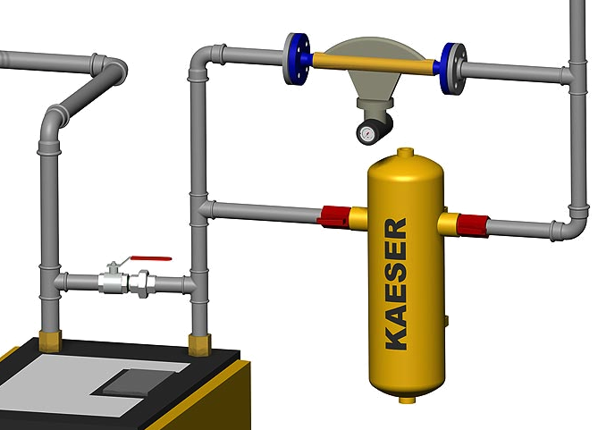
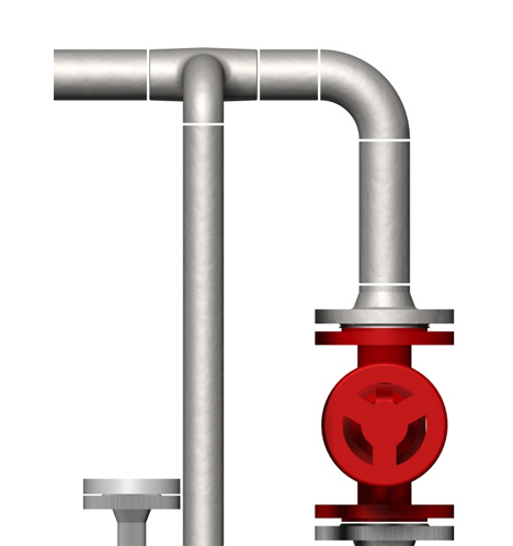
The insertion of additional components (e.g. fittings and instruments) in an existing pipe system is easily possible. Smap3D Piping draws from the utilized pipe spec definitions in the construction of the pipe system and permits only the installation of the appropriate specific components.
All symbols that have already been placed in the line progression are automatically turned when the flow direction is changed. Lines can be changed (elongated, shortened, shifted) with the use of “handles”.
Subsequent to their placing, Smap3D Piping recognizes the new situation and update the pipeline automatically. This method of operation achieves a high level of process security in 3D pipe system planning.
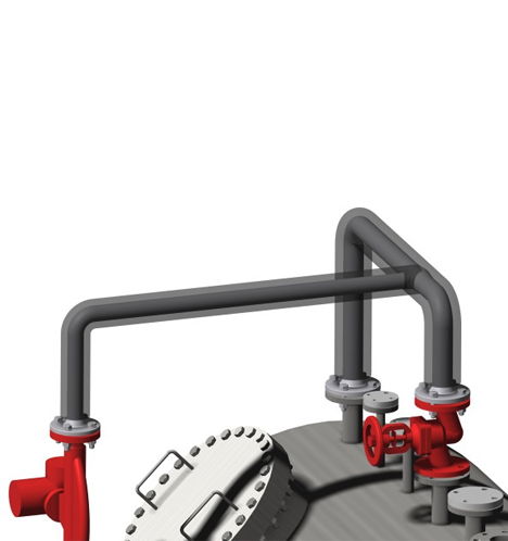
In alterations of the pipe system route (programmed toolpaths) the updating of the constructed pipeline (missing or superfluous fittings and pipes) is carried out fully automatically using the 'knowledge' of the utilised pipe specs.
In alterations to the composition of existing pipelines, for example, in changes to the pipe spec, the diameter, or another pipe spec feature, Smap3D Piping proceeds in the same way and uses the memorised definitions from the pipe specs.
For the generation of reduced or extended pipelines the user must determine only the required diameter and position of the reduced or extended components. The placement of the components as well as the complete modification of the changed pipeline parts to the new diameter are carried out by Smap3D Piping.
In all automatisms offered by Smap3D Piping, the user is still in the position to extend and edit a pipe system according to their individual requirements, with the use of different functions, e.g. 'Use undefined components', 'Place parts' etc.
Smap3D can be used with SolidWorks & SolidEdge
Get Free Live DemoMain functions of 3D pipe system construction
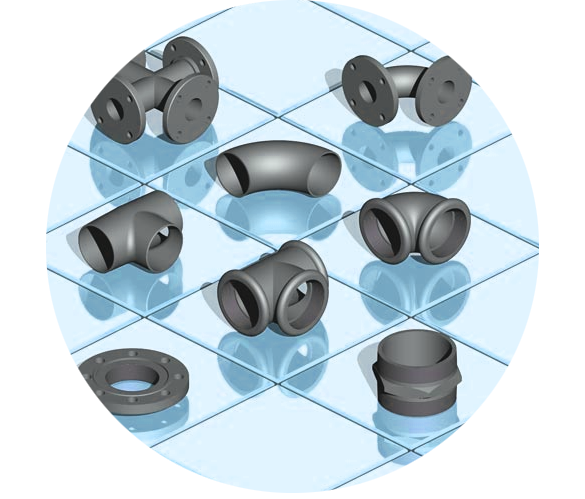
In pipe system construction with Smap3D Piping a large number of automatic placing routines (QuickPlace methods) for fittings in 3D pipelines are available.
The most important of these are the automatic placement of:
- Bends (for all common angle values)
- Tees normal and reduced (for all common angle values)
- Collars/Weldolets instead of reduced tees (for all common angle values)
- Flanges and gaskets
- Generation of straight pipes between the fittings
- Generation of bend pipes when no bend fittings are placed
Further intelligent automations and functions for pipeline planner´s assistance are:
- Automatic creation of pipeline reductions or expansion
- Automatic flow direction control
- Splitting of pipes when maximum length is reached
- Placement of connection components (e.g. Unions) when maximum length is reached
- Creation of weld gaps
- Placement of fitted bends for sloping pipelines
- Creation of insulations
- Quick and easy addition of new automations through QuickPlace methods
Reductions or extensions
Welding gaps
Insolation
Smap3D can be used with SolidWorks & SolidEdge
Get Free Live DemoFunctions for non-round pipes
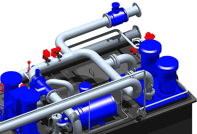
When constructing pipelines with pipe specs, Smap3D Piping can also be used to create any non-round profils. Cable ducts, routes, air ventilation ducts etc, can be quickly and efficiently built in the 3D assembly. In the process, the software uses similar fully automatic placement routes, as with round profils.
The most important of these are the automatic placement of:
- Shape bends with 45 and 90 degrees
- Shape tees with 45 and 90 degrees with identical and reduced profils
- Shape flanges and washers
- Flanges and gaskets
- Generation of form-pipes between the placed shape fittings
- Placement of pipes with fixed lengths
As a special function extention, the alignment of the particular components (left/right, as well as up or down) is taken into account.
- Automatic creation of pipeline reductions or expansion
- Automatic flow direction control
- Splitting of pipes when maximum length is reached
- Placement of connection components (e.g. Unions) when maximum length is reached
- Creation of weld gaps
- Placement of fitted bends for sloping pipelines
- Creation of insulations
- Quick and easy addition of new automations through QuickPlace methods
Smap3D can be used with SolidWorks & SolidEdge
Get Free Live DemoYour Advantages
- Take over of all P&ID definitions when “work connected” with” Smap3D P&ID.
- Comprehensive 3D-standard parts library available
- Library easily extended with any components
- Automatic generation of complete pipe systems
- Flexible placement of additional components (interactive or controlled from Smap3D P&ID)
- Automatic updating after alteration
- Allowance for sloping gradients
- All tools necessary for pipe spec creation and maintenance included
- Simple usage and fast user-acceptance
- One single tool to construct round and non-round pipelines
- Collision detection via functions of the base CAD system
- Automatic drafting via functions of the base CAD system
- Automatic construction of bills of materials
- Automatic construction of pipeline isometries with Smap3D Isometric
- 'Walk-through' animation via functions of the base CAD system
- And much more…
 \
\
Smap3D can be used with SolidWorks & SolidEdge
Get Free Live Demo