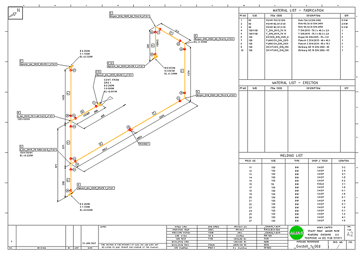
Isometric for Pipeline Manufacturing
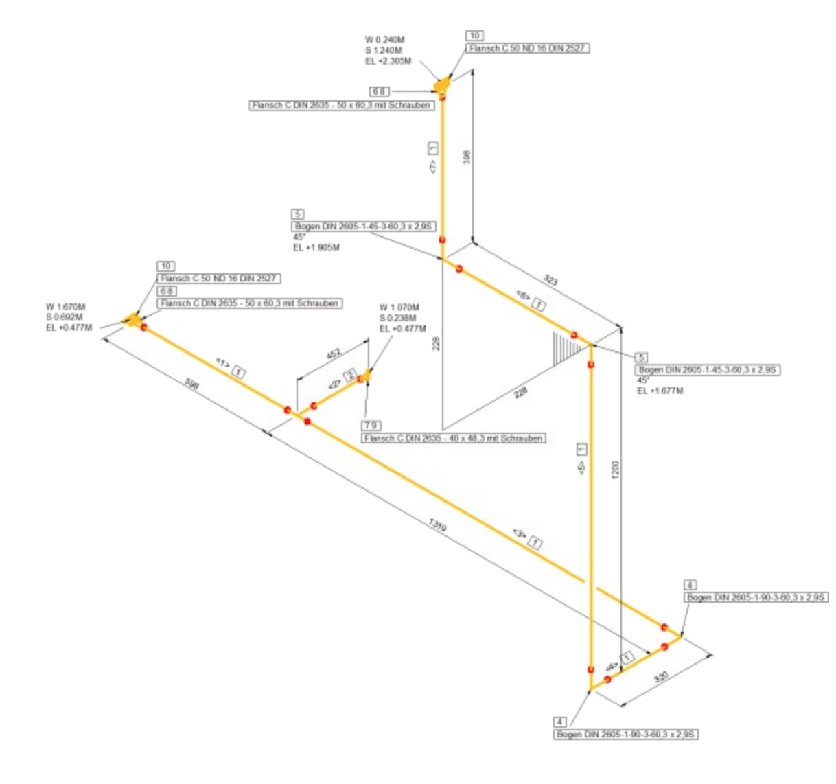
Isometric is the third item of the typical process chain in plant design. Pipeline isometric is a technical drawing in the form of an isometric image for the design and manufacture of pipelines. Pipeline isometric shows the pipeline not to scale and simplified with all its details and dimensions in length, width and height, in which the main axes of the three dimensions cross under 60°.
Our plant design solution is simple to install and use and it's considerably better priced than another particular 'big' plant design system. We close the gap between plant, apparatus and mechanical engineering!
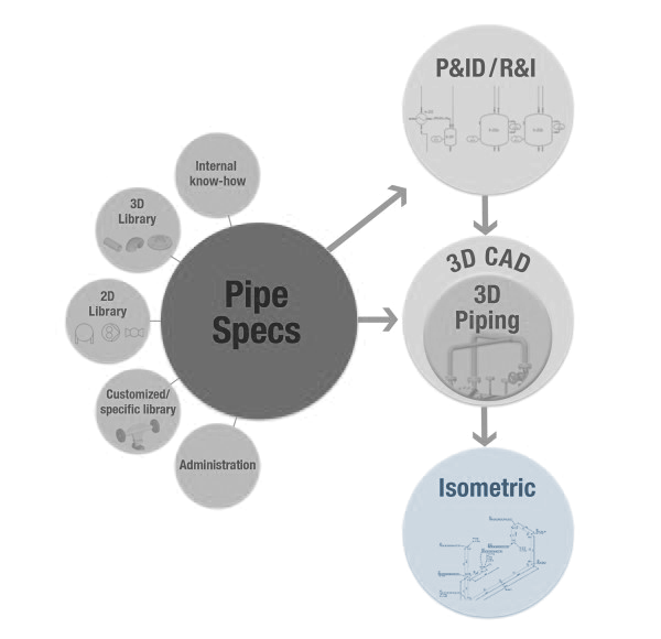
The simplest way to create isometrics is with market leader ALIAS (Intergraph) basis technology. For the generation of pipeline isometrics, we offer the integrated solutions Smap3D Isometric für SOLID EDGE® and for Solid Works®.
Smap3D Isometric for SOLID EDGE® and for SOLIDWORKS®
Smap3D Isometric exports all information to the 3D pipelines, creating the isometric drawing fully automatically. ISOGEN®, from market leading ALIAS (Intergraph) is the basis software. Both products belong to the market leaders in their areas and offer an outstanding price-performance ratio. In combining both systems, a productive co-operation is achieved from which both mechanical engineers and plant constructors benefit.
- Pipeline isometrics are created from the 3D assembly unit in 3D CAD at the click of a button.
- Desired customizations and configurations (Rules and property assignment) can made user-friendly in Smap3D Isometric user interface.
- Smap3D Isometric adopts the generated 3D pipelines (developed via Smap3D Piping) with every assigned component and feature and delivers these via the PCF format to the integrated ISOGEN®
- ISOGEN® processes all the available information and automatically creates out of it the isometric drawing DXF, DFT, SLDDRW or DGN (MicroStation) format.
The positioning of the pipeline mappings, as well as all corresponding information, such as dimensions, skew hatching, notations, follow completely automatically over presettable parameters (styles). Line names and spatial coordinates are also taken from the assembly unit and automatically assigned. Diverse bills of materials (BOMs) – (whether material-, blank-, welding piece lists etc) can, as an option, also be automatically issued on the drawing, and/or as ASCII-Data to the ERP system.
Creating parts lists on the isometric drawing
The image and content of an automatically generated isometric drawing are completely configurable. 10 pre-configurable styles are delivered with the software installation. These may be used as they are, or, whatever the requirements, changed or adapted using the included ISOGEN I-Configure functions. With Isometric Symbol Editor you can create your own isometric symbols.
When creating isometrics, the parts lists can be recognized and processed further by the integrated ISOGEN® system. Highly variable parts lists - e.g. lists of material, cutting and welding parts - can be automatically generated (either on the drawing and/or as an ASCII file) for transfer to an inventory management system.
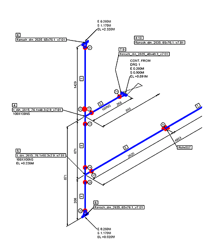
A drawn line becomes a logical pipeline after the pipeline features are assigned (pipeline number, pipe class, DN, etc.). All the available information about the pipeline can then be envisioned from the drawing.
Samples for BOM content:
- Automatic evaluation of cut length for single pipes
- Automatic evaluation of total length
- Automatic evaluation (count) of required fittings and components
- Automatic evaluation filtered to "Fabrication“ and "Erection“
- Automatic evaluation to required welds
Advantages when using isometrics
- Isometrics and reports are generated automatically from the 3D model.
- User-friendly default configuration in Smap3D Isometric.
- 100% customizable with ISOGEN I-Configure and Isometric Symbol Editor
- User-friendly default configuration in Smap3D Isometric.
- 100% customizable with ISOGEN I-Configure and Isometric Symbol Editor
Smap3D can be used with SolidWorks & SolidEdge
Get Free Live Demo