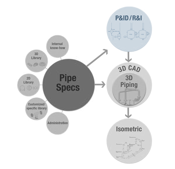
2D Flow Diagrams (P&ID)
Features
2D Symbols and Geometry
In addition to the built-in symbol libraries (ISO/DIN, ANSI/ISA), you can also integrate your own symbols (2D geometry in DXF or DWG format) or use the “symbol generator” to conveniently and quickly create new symbols specific to your company. When placed in a drawing and/or built into a line, symbols are scalable, aligned with a snap grid and respond logically. The turning of symbols and line separation is entirely automatic. “TAG numbers” and further characteristics are also prompted automatically.
Component Information
Company or project-specific components of any kind can be entered in the component databank. If the required symbols must be assigned to components when placed into a drawing, all of the component information – not only the symbol geometry - is transferred to the project automatically. “TAG numbering” prompts also occur automatically. All available information can then be envisioned from the drawing.
Dynamic Lines (Pipelines)
3D-CAD software for pipeline planning – 2D flow diagrams
Our dynamic lines make drawing and processing pipelines easy. By automatically separating or closing, the lines respond dynamically to the addition or removal of symbols/components. Lines no longer need to be reworked manually. These smart lines allow the flow direction display (arrow) to be turned on and off easily.
All symbols that have already been placed in the line progression are automatically turned when the flow direction is changed. Lines can be changed (elongated, shortened, shifted) with the use of “handles”.
A drawn line becomes a logical pipeline after the pipeline features are assigned (pipeline number, pipe class, DN, etc.). All the available information about the pipeline can then be envisioned from the drawing.
Testing (Validation)
“Design Checks” can be used to review individual P&ID drawings as well as the entire project for completeness, plausibility and accuracy. Included among others:
- Flow direction check
- Duplicated or missing tag numbers
- Conformity of the diameter at the connection point and line
The flexible software structure enables quick and easy addition of customized design checks.
Evaluations and Reports
Project sheets and exported data for any BOMs and evaluations can be produced from all the assembled project information in the form of symbols, components and pipelines. The following formats are supported for export and their contents are 100% configurable, storable and reusable: XML, Microsoft® Excel® , comma or column separated text data
Smap3D can be used with SolidWorks & SolidEdge
Get Free Live Demo